Fitbit Aria Teardown
- Updated 17 November 2016 with Fitbit Area UART1 terminal logs.
- Updated 20 November 2016 with Fitbit Area UART1 interactive mode.
Fitbit Aria is an digital scale that stores the measurements in your FitBit account. It’s the best digital scale I’ve used, but also the most expensive.
After driving 17 hours with the Aria packed in our luggage it stopped working, displaying only:
“Step On… Sensing… Thinking… ERR”
which is a sensing error described at fitbit help. None of the steps suggested help articles made any difference, so I assumed the sensors had been damaged (squashed too much). The Fitbit support team tried to help, and even offered to replace the unit, but I decided to try to work it out for myself.
Fitbit Aria Teardown
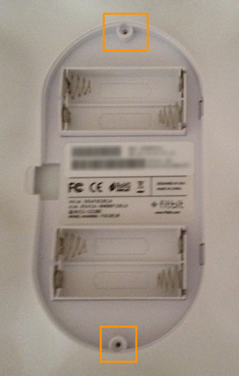 Undo the two screws behind the Aria adjacent to the battery compartment:
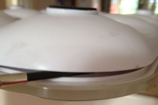 Using a thin flathead screwdriver, carefully separate the entire rear cover from the front. It needs to lift around 2cm, so work around each corner raising it a little at a time. Be careful to not separate the rubber seal that’s glued to the glass.
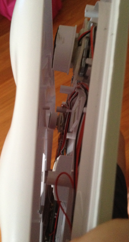 It will eventually start to separate. The case will try to bite your finger if you stick it in there too soon.
 The main board and sensors are screwed to the chassis behind the glass.
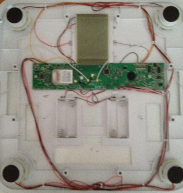
Starting with the sensors, there’s four typical load sensors, one mounted under each foot of the scale. These look like standard strain gauge sensors using a wheatstone bridge to measure tiny variances in the resistance as force is applied to the sensor. Each sensor has three wires: a common ground, excitation and sensor, which each lead to the main board.
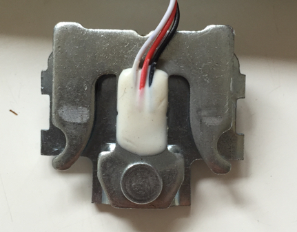
I guess these sensor outputs connect to an amplifier on the main board before going to the ADC of the microprocessor. One of the sensors also includes a contact switch that provides the signal that someone has stepped on or off the scale. Don’t open it open because it’s a bitch to get back together again.
My hypothesis is that once of these sensors has been bent through excessive force and no longer outputs a meaningful sense voltage. They’re pretty sturdy though. The plastic frame of each sensor also appears to provide a little bounce-back so perhaps just the plastic is bent too much. Aside from testing the sensors individually I’m not sure how to check that.
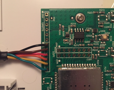
Taking a look at the main board:
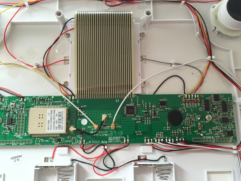
The beautiful custom LCD is driven by a HOLTEC HT1623 RAM Mapping 48x8 LCD Controller. The controller features a serial input that’s used to load data into RAM to set the value for each of the 48x8 segments. The controller does the rest of the work to drive the LCD.
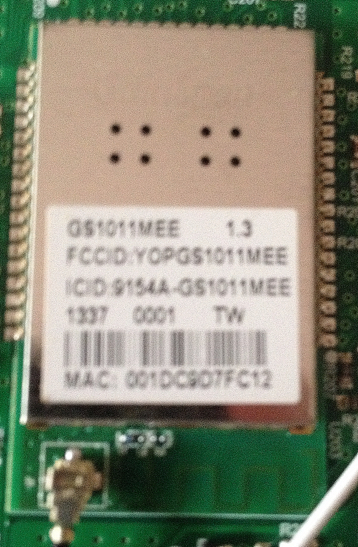
To the left of the mainboard is the GainSpan GS1011MEE WIFI Module. These modules are great as they provide everything needed in a single PCB module that has serial and other interfaces to controller it. The module is connected to two embedded antenna by Ethertronics mounted at the sides of the scale.
Unfortunately the main IC in a “Chip on Board” package which means I can’t see what it is (the black blob of epoxy). The underside of the mainboard just includes test points and various routes.
Taking a look around the main IC are peripheral chips that help with the I/O:
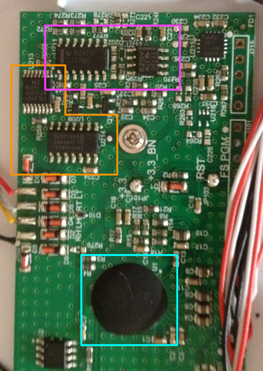
The larger peripheral chips include:
- 4066 single pole analog switches, and NX3L2467 double pole analog switches highlighted in orange, that provide a output (high/low) depending on whether the analog input passes a threshold, as well as lots of other D->A or A->D applications. I can only guess what they’re all used used for. One potentially helps detect a “tap” on the scale which is one of the ways to control it.
- TLC274 operational amplifiers, highlighted in purple. I’d guess the op amps amplify the signals form the load sensors so they’re by the ADC inputs of the main chip.
The main chip is probably a standard embedded controller with digital I/O, some ADC inputs and serial I/O. I can’t tell what it’s using to communicate with the GainSpan Wifi.
Unfortunately no amount of non-destructive fiddling could make the sensing error go away. If you have some ideas or know me than me please leave a comment.
Update with Terminal Logs: 17 November 2016
Motivated by comments below from Jordan Heywood and John Blackmore I connected a terminal to UART1 of a working Fitbit Aria. I used a FTDI TTL-232RG-VIP-WE.
- First power-on after inserting battery
- Tap power button - wake up and sleep immediately
- Tap power button and hold - wake up
- Full measurement and attempting to store
I don’t have the unit that failed anymore but these logs may help others. The main difference seems to be the working unit successfully gets a tare while the others fail. The “readn checksum mismatch” seems to be normal. I don’t think it’s a problem in the software/firmware but at the sensor output/analog input.
Update with Terminal Logs: 20 November 2016
The UART1 port is interactive. After power-on from battery type “?” to get to the console.
Type help for a list of common commands.
Extract:
> calchk
Scale controller firmware version 15
Calibration already complete, calibration data count: 20
readn checksum mismatch: 07d9!=ffff
Recoverable error 3. Retrying operation.
...
> fwver
Flojo App version 39, WFW version 2c0200
END.
> hwrev
HW rev: 8400019
END.
> deviceid
App: 39
WFW: 2c0200
LCD: ht16c23
Scale: Fortune_v15
00 00
MSP430: pass
Flash: pass
END.
I didn’t learn anything actionable from the console but others may be able to test their defective units. Please post back if you learn something. References to the scale processor as “Fortune” point to one of measurement ICs by Fortune